In Part 1, Section 1.3 we have discussed strain gauges. Strain gauges belong to the class of modulator type transducers: their electrical resistance depends on the amount of deformation but there is no energy stored in the transducer and there is no energy flow from one physical domain to the other. Instead, we can describe these transducers by a blank energy flow in the information receiving domain which is modulated by the information in the other domain. We will now start with another type of transducers: generator type transducers. In generator type transducers the transduction is related to a flow of energy through the transducer and energy can also be stored in the transducer. These transducers can be described in a general way, independent of the domains that are involved.
In Part 2 and Part 3 of the course we will discuss a first class of generator type transducers: electrostatic or capacitive transducers. We will start our discussion by showing a few basic capacitor topologies. Next, we will refresh our knowledge about electromagnetic field theory and calculate the energy stored in a parallel plate capacitor. We will see that once we know the so-called energy function of the transducer, i.e. the energy stored in the transducer as a function of the variables at the input and output ports, we know virtually everything.
Figure 2.1.1 shows two basic capacitive transducer configurations. We will use these two configurations as example throughout the chapter. The theory can easily be extended to other capacitor configurations.
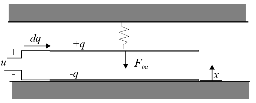
(a) Parallel plate capacitor with one fixed plate and one moveable plate suspended by a spring so that the distance between the plates can change.
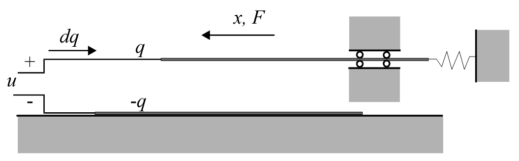
(b) The same parallel plate capacitor, but now the moveable plate is suspended such that only the overlap between the plates can change.
Figure 2.1.1: Two basic capacitive transducer configurations.
The most obvious application for an electrostatic transducer is that of a position sensor: with a constant charge on the capacitor plates the voltage will be proportional to the distance between the plates. However, it can also be used to control the position: the charge or voltage on the plates can be used to control the electrostatic force between the plates and thus change the position of the moveable plate. In fact, these are only two examples of many possible applications. E.g. one can also think of using the transducer as force sensor, charge or voltage meter, or charge or voltage generator.
In micro sensors capacitive transducers are often used for detecting the displacement of a moveable structure. For example, in a pressure sensor the membrane deflection due to a pressure difference can be measured or in an acceleration sensor the displacement of the proof mass can be detected. By changing the voltage or charge on the capacitor plates it is possible to control the deflected membrane or the proof mass back to the initial position. In that case the voltage or the amount of charge that is needed becomes a measure for the pressure difference or acceleration that is measured.
Figure 2.1.2 shows two examples of accelerometers using electrostatic transduction. The photograph on the left shows a large silicon proof mass that is suspended above an electrode. The proof mass itself is conducting and forms the other electrode of the capacitor. This structure is almost identical to the situation sketched in Figure 2.1.1(a). The photograph on the right shows the sensor element of a commercially available accelerometer. It consists of a thin proof mass that is fabricated in a thin silicon layer on top of the substrate containing the read-out electronics. Narrow ‘fingers’ are attached to the proof mass and each of these fingers is located between two fixed fingers that are attached to the substrate. Such a configuration is often called a ‘transverse comb drive’. In addition to detecting the position of the proof mass, it can be used to apply an electrostatic feedback force to keep the proof mass in the equilibrium position. By applying suitable bias voltages it can even be used to adjust the resonance frequency of the mass-spring system. In that case, due to the applied bias voltages the structure will act as an electrostatic spring in parallel to the mechanical spring suspension and the spring constant becomes a function of the voltages.
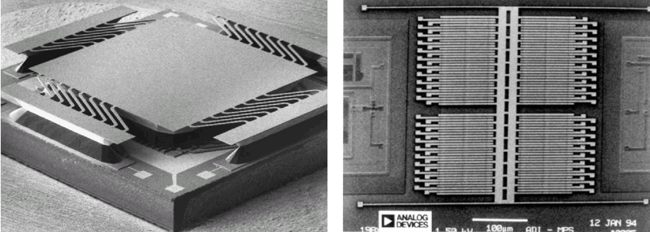
Figure 2.1.2: Two examples of electrostatic transducers used in micro sensors. Left: a parallel plate capacitor to detect displacements of a suspended proof mass in a vibration sensor (Bernstein 1999). Right: Surface micromachined accelerometer, the ADXL-50 from Analog Devices, using a so-called transverse comb drive for both displacement detection and electrostatic force feedback.
Even more complicated sensor structures are shown in Figure 2.1.3. This figure shows photographs of angular rate sensors. In both cases a micromachined structure is brought into vibration. When the chip is rotated, some of the vibration energy is coupled into another vibration mode. The amplitude of the secondary vibration is detected and the resulting signal is proportional to the rotational speed, i.e. the angular velocity.
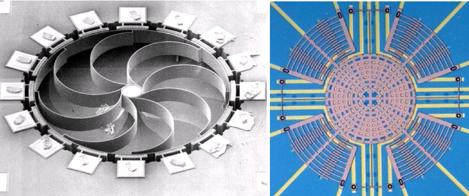
Figure 7.3: Two examples of micromachined angular rate sensors or gyroscopes. The structure on the left consists of a ring with 16 electrodes around the circumference. The electrodes are used to bring the ring into vibration and to detect the amplitude of a secondary vibration that is proportional to the angular velocity. The structure on the right consists of a thin micromachined plate with so-called comb drives attached to it. The comb drives are used to bring the disk into a rotational vibration around its centre. A rotation of the structure will result in tilting of the plate with respect to the substrate underneath it. This tilting is detected using electrodes that are located on the substrate under the vibrating plate.