A Coriolis mass flow sensor consists of a vibrating tube in which a mass flow will experience Coriolis accelerations. The latter will result in a secondary vibration mode with a vibration amplitude proportional to the mass flow. Several different designs of micro Coriolis mass flow meters have been published, both with electrostatic and magnetic actuation, see Figure 1. Today we would like to compare these two techniques to generate the vibration and decide which one is better.
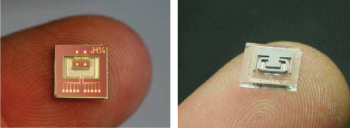
Figure 1. Two micro Coriolis mass flow sensor chips. Left: sensor developed at the MESA+ institute using magnetic actuation (through a wire on top of the tube and an external magnetic field). Right: sensor developed by ISSYS using electrostatic actuation (through electrodes underneath the tube).
In order to decide which actuation method is the most suitable, of course we first need to understand the operating principle of a Coriolis mass flow sensor which is illustrated in Figure 2. The tube has a rectangular shape, with dimensions Lx = 2.5 mm and Ly = 4 mm. For maximum sensitivity, the vibration amplitude should be as high as possible. Should we choose electrostatic or magnetic actuation for our next design?
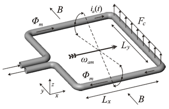
Figure 2. Operating principle: the tube has a rectangular shape and is vibrated in the so-called ‘twist’ mode indicated by ωam. A mass flow Φm through the tube generates Coriolis forces Fc which result in a second vibration in the ‘swing’ mode. The amplitude of the swing mode vibration is directly proportional to the mass flow. Actuation of the tube can be done by an external magnetic field B in combination with an AC current ia.