Let's now first have a look at a practical example: the ADXL-50 accelerometer chip from Analog Devices.
Figure 2.7.1 shows a photograph of the mechanical element in this chip. In the center of the chip we see the proof mass, which can move in the up-down direction and is suspended by four springs consisting of the slender horizontal beams in each corner. The four springs are anchored to the substrate by the little squares at their ends. At the sides of the mass we see fingers sticking out. Each finger that is connected to the mass is in between two fingers that are anchored to the substrate. When the mass moves, the distance between the fingers changes, resulting in a change in capacitance.
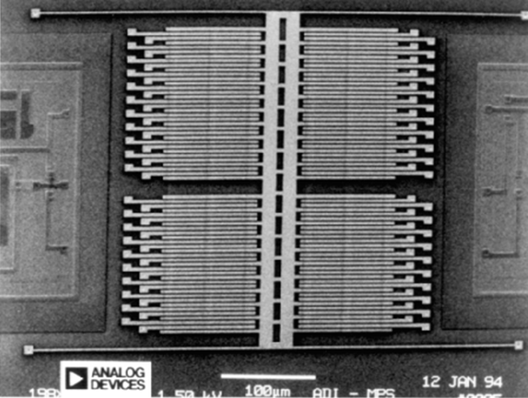
Figure 2.7.1: ADXL-50 Accelerometer from Analog Devices.
Figure 2.7.2 shows a close-up of the fingers. A structure like this is called a transverse comb. The fixed fingers at each side are electrically connected to each other. The schematic drawing in Figure 2.7.2 shows how the capacitance between the fingers changes if the mass moves. If the mass moves to the right, the capacitance between the moving fingers and the "green" fingers increases, and the capacitance to the "blue" fingers decreases.
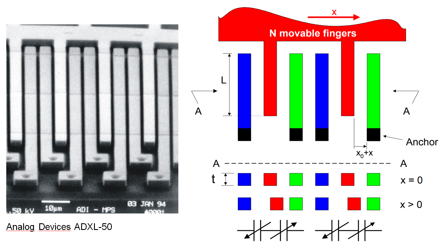
Figure 2.7.2: Left: close-up of the transverse comb structure. Right: Schematic drawing indicating how the capacitance between the fingers changes with the position of the proof mass (from: B.Boser, Sensor Interfaces, 1996).
In the ADXL-50 accelerometer the transverse comb structure is used for three purposes:
1.To measure the position of the mass by detecting the difference in capacitance between the mass and the "blue" and "green" fingers. AC voltages with same amplitude but opposite phase are supplied to the "blue" and "green" fingers. If the mass is in the center, no AC voltage is detected on the mass. If the mass is displaced, there will be an AC voltage with an amplitude proportional to the displacement (and the phase indicates the direction in which the mass has moved).
2.To apply a feedback force to the mass by controlling the voltage on the mass. In this way the mass is kept in the center position and the voltage needed for that is a measure for the acceleration. The electrostatic force is proportional to the voltage squared (see equation (2.31)). By applying a voltage V0+Vx at one side and V0-Vx at the other side the net force will be linear with both V0 and Vx. Try to figure this out yourself!
3.To increase the sensitivity by having a negative electrostatic spring in parallel with the mechanical suspension. This is achieved by applying equal bias voltages at both sides. The net force will then be zero (the forces will be equal and cancel each other), but the electrostatic spring constant (see equation (2.34)) adds up.
Figure 2.7.3 shows a block diagram of the ADXL-50 from the datasheet. Can you recognize the operation of the 3 different functions of the transverse combs?
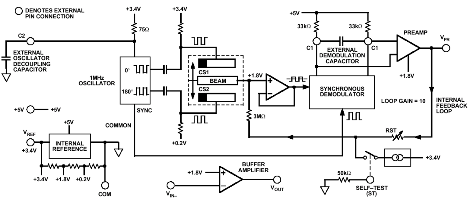
Figure 2.7.3: Block schematic of the ADXL-50.